Write-buffered Registers
In order to support larger software write accesses that are atomic, the regblock generator understands several UDPs that implement write-buffering to specific registers. This causes the regblock to delay the effect of a software write operation until a defined trigger event.
- Some examples of when this is useful:
You need to have software update a wide 64-bit register atomically, but the CPU interface is only 32-bits.
Software needs to be able to write multiple registers such that the hardware is updated atomically.
Software can pre-load one or more registers with their next value, and trigger the update via an external hardware signal.
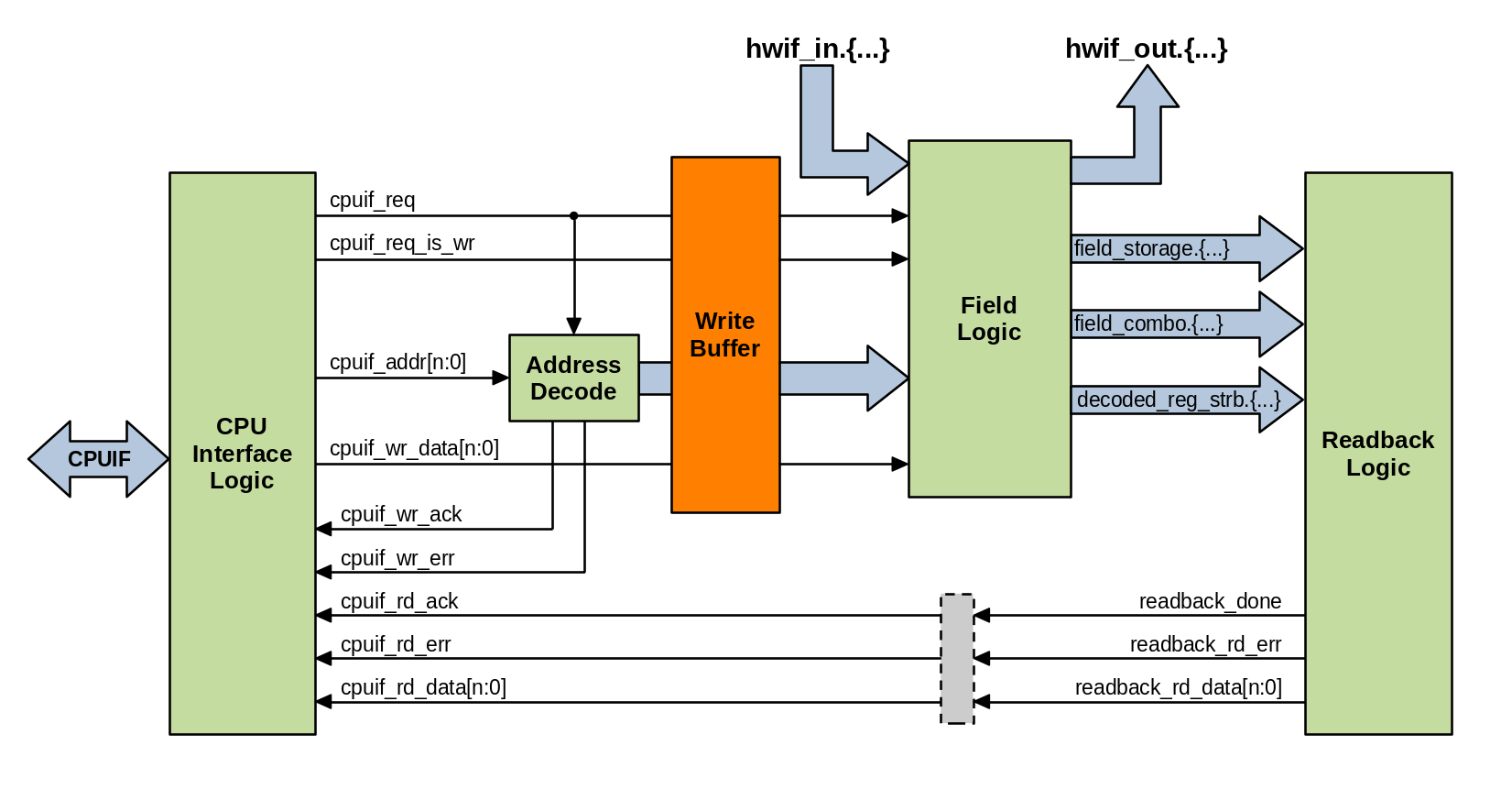
If a register is write-buffered, a holding buffer stage is inserted between the decode logic and the field logic. This effectively defers any software write operations to that register until a trigger event occurs that releases it. Write buffering storage is unique to each register that enables it. If a register is not write buffered, this buffer stage is bypassed.

Properties
The behavior of write-buffered registers is defined using the following two properties:
property buffer_writes {
    component = reg;
    type = boolean;
};

property wbuffer_trigger {
    component = reg;
    type = ref;
};
These UDP definitions, along with others supported by PeakRDL-regblock can be
enabled by compiling the following file along with your design:
regblock_udps.rdl.
- buffer_writes
Assigned value is a boolean.
If true, enables double-buffering of writes to this register.
Any software write operation to a buffered register is held back in a storage element unique to the register.
The software write operation is committed to the register once triggered to do so.
Unless specified otherwise, the buffer trigger occurs when the highest address of the buffered register is written.
- wbuffer_trigger
Assigned value is a reference to a register, single-bit field, signal, or single-bit property.
Controls when the double-buffer commits the software write operation to the register’s fields.
If reference is a single-bit value (signal, field, property reference), then the assertion of that value triggers the buffer to be evicted.
Signal references shall have either activehigh/activelow property set to define the polarity.
If the reference is a reg, then buffer is evicted when the register’s highest address is written.
Other Rules
It is an error to set
buffer_writesif the register does not contain any writable fieldsIf
buffer_writesis false, then anything assigned towbuffer_triggeris ignored.The buffered register and the trigger reference shall both be within the same internal device. ie: one cannot be in an external scope with respect to the other.
Unless it is a register, the reference assigned to
wbuffer_triggershall represent a single bit.If a buffered register was not written, any trigger events are ignored.
It is valid for a buffered register to be partially written (either via write strobes, or partial addressing).
The software write operation is not considered to take place until the buffer is evicted by the trigger. This influences the behavior of properties like
swmodandswacc- they are not asserted until the register’s fields are actually written by the buffer.
Examples
Below are several examples of what you can do with registers that are write-buffered.
Wide Atomic Register
Without write-buffering, it is impossible to update the state of a 64-bit register using a 32-bit CPU interface in a single clock-cycle. In this example, it still requires two write-cycles to update the register, but the register’s storage element is not updated until both sub-words are written. Upon writing the 2nd sub-word (the higher byte address), the write data for both write cycles are committed to the register’s storage element together on the same clock cycle. The register is updated atomically.
reg {
    regwidth = 64;
    accesswidth = 32;
    buffer_writes = true;
    field {
        sw=rw; hw=r;
    } my_field[63:0] = 0;
};
Atomic Group of Registers
Perhaps you have a group of registers that need their state to be updated
atomically. Using the wbuffer_trigger property, you can define which
register write operation triggers the group to be updated.
reg my_buffered_reg {
    buffer_writes = true;
    field {
        sw=rw; hw=r;
    } my_field[31:0] = 0;
};

my_buffered_reg reg1;
my_buffered_reg reg2;
my_buffered_reg reg3;

reg {
    field {
        sw=rw; hw=r;
    } my_field[31:0] = 0;
} reg4;

reg1->wbuffer_trigger = reg4;
reg2->wbuffer_trigger = reg4;
reg3->wbuffer_trigger = reg4;
In this example software may pre-write information into reg1-reg3, but the register write operations do not take effect until software also writes to reg4. The write operation to reg4 triggers the buffered data to be committed to reg1-reg3. This is guaranteed to occur on the same clock-cycle.
Externally Triggered Register Update
Some applications may require precise timing for when a register (or group of registers) update their value. Often software cannot offer such timing precision.
In this example, the trigger event is bound to an external signal. When asserted, any pending write operation the buffered register will be committed. The hwif_out value presents the new register state on the clock cycle after the trigger is asserted.
reg my_buffered_reg {
    buffer_writes = true;
    field {
        sw=rw; hw=r;
    } my_field[31:0] = 0;
};

my_buffered_reg reg1;
my_buffered_reg reg2;

signal {
    activehigh;
} trigger_signal;
reg1->wbuffer_trigger = trigger_signal;
reg2->wbuffer_trigger = trigger_signal;
After software writes to reg1 & reg2, the written data is held back in
the write buffer until hwif_in..trigger_signal is asserted by the hardware.